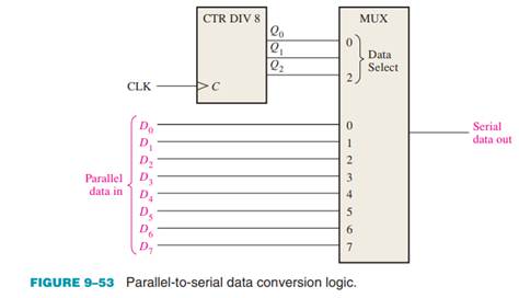


In a computer, it decreases the number of copper lines necessary to connect the memory to other parts of the computer.It also works as a parallel to serial data converter.In satellite communication, multiplexers transfer data from the satellite’s computer system to the ground segment using GSM communication.In optical fiber communication, a multiplexer does the same job to combine multiple fiber cables onto one fiber cable using a technique called Dense wavelength division multiplexing.

In a communication system where we have a communication network, a multiplexer increases the efficiency of the system by allowing the transmission of audio and video data on a single channel.The applications of a multiplexer include Plotting the circuit for the above equation we get the following logic circuit for a 4:1 multiplexer.Ĥ:1 multiplexer circuit design What are the uses of a multiplexer? Output is 1 when I0 = 1 and S0 = 0 and S1 = 0 OR when I1 = 1 and S0 = 0 and S1 = 1 and so on we get Solving for output using the method we saw in the post for comparators. S0S1 = 00 (0 – decimal value), I0 is connected to the output. X is don’t care because that particular line is not selected by the control lines’ values. I0 I1 I2 I3 S0 S1 Output 0 x x x 0 0 0 1 x x x 0 0 1 x 0 x x 0 1 0 x 1 x x 0 1 1 x x 0 x 1 0 0 x x 1 x 1 0 1 x x x 0 1 1 0 x x x 1 1 1 1 For n inputs, m select lines, where n=2^m. If you are unable to answer these questions, you still have the formula we saw above to count on. We have four inputs, what number of digits in a binary number gives you four possible combinations? Or, using how many digits in a binary number can you count up to four? Let’s now design a 4:1 multiplexer circuit.Ĭan you calculate how many select lines would be present in this mux? Now, as we increase the number of inputs, the number of select lines will increase too. In this way, the multiplexer acts as a switching circuit. The current value on the line that is selected passes to the output. Output = SI1 + S’I0 2:1 multiplexer circuit designĪs we can see in the multiplexer circuit, depending on the value of the select line (S), we can select an input line to connect it to the output. I0 I1 S Output 0 0 0 0 0 0 1 0 0 1 0 0 0 1 1 1 1 0 0 1 1 0 1 0 1 1 0 1 1 1 1 1įrom the k-map of the above truth table we get


 0 kommentar(er)
